Polymer & Co.
Object Design
Specifications for the object design
To design an object for 3D printing, there are different steps to follow:
-
Have an idea of your object
-
Use a 3D design program to design the object
-
Use a slicer program to cut the object in different slices that will be printed by the 3D printer
-
Print your object
But for the final object, we had also some specific instructions to respect:
-
It has to resist over 120°C
-
We have to use at least 2 different materials displaying significantly different properties
-
Be articulated, at least one part should be able to move with respect to another one
-
Requiring a minimal amount of polymer to minimise the cost, weight and ecological footprint
With these guidelines in head, we thought to make pliers which would be able to take some object(s) in an oven which could be heated over 120°C.
Design softwares


The programs that we have used for the design are Tinkercard, a free program online, and 123D design, which on the one hand gives a better object performance but on the other hand requires an improved computer performance.
As slicer program, we used Makerware to switch the .stl files of the design to .x3g for the printing.
But how works a 3D design program?
We must build each part of the final object by adding some small pieces all together. Sometimes we had to make hollow structures to decrease the amount of polymer used. We scaled each part of the object in agreement with the others.
Our final design for the pliers is shown just below:
Our Design
The mechanism is based on the movement of a piston and its joints. The black dots represent the joints allowing the clamp to open and close. If we pull on the handle (red arrow), the piston goes down in the cylinder. Thanks to the rotation points at the front of the cylinder, the movement of the piston leads to the opening of the clamp. If we push the handle (green arrow), the piston will goes up in the cylinder leading to the closing of the clamp. To improve usability, a spring will be placed behind the piston so that the closing is automatic. Therefore, the catching force is directly proportional to the spring force constant.
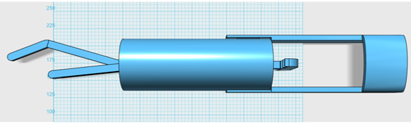
Figure 1A : Final design of the clamp
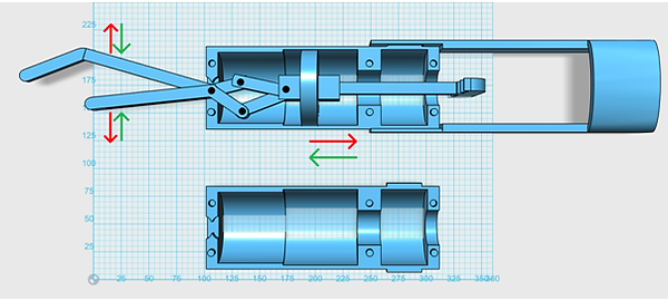
Figure 1B : Final design of the clamp
For the practical part, the two cylinders are attached together by points and holes. To improve the ease of printing and implementation, the holes for the joints will be done manually with a drill and rivets will be used for the axes of rotation. The clamp will be attached to the wrist by velcro fasteners, this way, any hand size will be possible.
For the materials part, we need a robust polymer because it will have to endure a significant force. Therefore, Nylon 230 will be used for the mecanical part. Another polymer will be used to improve the adhesion between the object to catch and the clamp, the nGen_flex. This polymer will be printed and added like a glove above the clamp.
This is the final object after printing at 1/2 scale with the white parts in Nylon 230 and the black ones in nGen_Flex, and without the second half pipe, to see the mechanism :

Due to the reduced scale (1/2 for the height, width & length) the final object is much smaller than the design model. This size made that the joints don't work well but also allows us to print quite faster (by a factor 5 gain ). The spring isn't in this version of the object, because it's a reduced model. Also, some pieces of the clamp have been hard to print, like the two half pipes, due to the warping of the polymer and the accuracy needed on these parts. Lastly, almost all parts needed a support to facilitate the printing and avoid defects in the final structure.